Background:
The ARB Air Locker system in its stock configuration does not allow use of the front differential locker unless the rear differential locker is also engaged. Use of a front locker has shown to be very beneficial in some cases, thus the desire to modify the current system. In a single locker system (front only), the front locker switch will be wired in place of the rear locker switch, thus no modifications are needed to allow its use.
Parts & Tools Required:
1. A short length of red wire (14-16 gauge)
2. A single female push-on connector (14-16 gauge)
3. Butt-connector or splice-tap (14-16 gauge)
4. Wire cutting, crimping & stripping tool(s)
Modifying the System:
1. Disconnect the vehicles battery.
2. Remove the switches from their mounting location, wiring does NOT have to be removed from the switched.
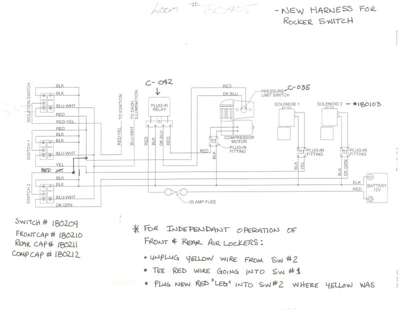
3. Remove the solid yellow wire from the back of the Front Locker Switch, note location.
4. Locate the solid red wire entering the back of the Rear Locker Switch.
Using a butt-connector:
5a. If using a butt-connector ONLY, cut the red wire several inches from the switch.
5b. Strip ~1/4" of shielding from BOTH ends of the ARB system red wire previously cut.
5c. Strip ~1/4" of shielding from the end of the NEW red wire (not the ARB system wire).
5d. Insert one end of the red ARB system wire (leading into the ARB harness) into the end of the butt-connector. Crimp accordingly.
5e. Insert BOTH the other end of the red ARB system wire (leading to the switch) and the NEW red wire into the opposite end of the butt-connector. Crimp accordingly.
Using a splice-tap:
6a. If using a splice-tap ONLY, strip ~1/4" of shielding from the end of the NEW red wire (not the ARB system wire).
6b. Place NEW wire into the the splice-tap, and place splice tap over the red ARB system wire several inches from the switch. Crimp splice-tap accordingly.
7. Locate original location of solid yellow wire as noted in #2 of instructions. Measure and cut NEW red wire to be attached here.
8. Strip ~1/4" of shielding from end of NEW red wire.
9. Place push-on connector at the end of the NEW red wire. Crimp accordingly.
10. Connect NEW red wire to the back of the Font Locker Switch in place of yellow wire as noted in #2 of instructions.
11. Reconnect vehicle battery & test locker independent locker functions.
Schematic:

Information contributed by:
Cruiser Outfitters
ARBUSA & TechTim
*See something missing, wrong, or incomplete? Please let us know!
Disclaimer: Cruiser Outfitters, cruiseroutfitters.com, its owners, contributors, employees and agents will not be held liable for damages and or injury under any circumstances for information presented accordingly. Furthermore, said agents reserve the right to modify/remove/edit all information accordingly.


